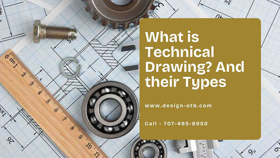
What is Technical Drawing? And their Types
- Seth Gilley
- 4 days ago
- 11 min read
Key Highlights
Technical drawings, also known as engineering drawings, serve as a universal language in various industries like manufacturing, engineering, construction, and architecture.
They provide detailed information about an object or structure, including its dimensions, geometry, materials, and assembly instructions.
These drawings use standardized symbols, line types, and abbreviations to ensure clarity and prevent misinterpretations.
From traditional hand-drawn sketches to sophisticated 3D models created using CAD software, technical drawings have evolved significantly.
Mastering technical drawing is an essential skill for professionals in various fields, as it facilitates effective communication, ensures accurate production, and maintains quality control.
Introduction
In a world focused on accuracy and detailed designs, technical drawing is an important skill and a shared language in many industries. A technical drawing, often called an engineering drawing, serves as a clear guide.
It provides a full set of instructions and details to turn an idea into something real. This skill helps change complex thoughts into images that people from different backgrounds can understand and use, overcoming language differences.
Understanding Technical Drawing
Imagine trying to build a house without a plan or putting together furniture without any steps. It would be a mess, right? This is where technical drawings help. They show a clear picture of something, making sure everyone understands it just like you do.
A technical drawing is a way to share detailed information about an object or structure, including the drawing number. It can encompass things like the size and shape of the object, what materials it utilizes, and how to assemble it.
Definition and Core Concepts
A technical drawing is a clear and detailed diagram used to show information about an object. It acts as a guide for design, manufacturing, construction, or engineering projects, as well as in technical documents related to these fields. Unlike artistic drawings, which can be seen in different ways, technical drawings follow specific rules and guidelines for accuracy, clarity, and easy understanding.
A key idea in technical drawing is orthographic projection. This method shows a 3D object using several 2D views, like the front, top, and side views. Each view gives key information about the shape and size of the object.
Technical drawings use standard symbols, line types, and notes to share complex information and details. This includes surface finish, material specifications, and manufacturing methods. All these elements create a clear visual language that is important for making ideas real in many industries.
Historical Development and Evolution
The history of technical drawing goes back to ancient civilizations. We can find examples in Egyptian hieroglyphs and Roman building plans. However, technical drawing really grew during the Renaissance. This time also saw new ideas in science and engineering. Leonardo da Vinci created detailed drawings of the human body and sketches of inventions. These works are key contributions from that time.
In the 19th century, industrial growth increased the need for standardized technical drawings. This period brought about mechanical drawing as a separate field. Gaspard Monge was one of the pioneers. He helped develop key ideas like orthographic projection and descriptive geometry. These ideas formed the basis for today's methods.
Now, the core principles of technical drawing still exist, but technology has changed things a lot. Computer-aided design (CAD) software has mostly taken over manual drawing. This technology allows for better accuracy, efficiency and makes it easier to create complex 3D models.
Essential Elements of Technical Drawings
A technical drawing has several key elements. Each element has a specific purpose. Lines are the most basic part. They come in different styles and thicknesses, including various types of lines. Lines show visible edges, hidden lines, centerlines, and more.
Dimensions and tolerances are also important in geometric dimensioning. They give numbers needed to make sure the final product meets the right specifications. There are also symbols and abbreviations. These help explain complex features or instructions quickly.
Common Lines and Their Meanings
In technical drawing, lines are not just simple lines. They are important tools that show a lot of important information about the shape and details of an object. Each line type has a special meaning. This helps to keep things clear and avoids misunderstandings.
For example, thick, solid lines show visible edges. These are the edges we can see from a certain angle. In contrast, dashed lines point out hidden lines. These lines represent edges that exist but cannot be seen from that view.
Additionally, thin chain lines act as centerlines. They mark the axes of symmetry and the center points of round features. This smart mix of different line types allows a technical drawing to share the necessary information about the structure and shape of an object.
Symbols and Abbreviations Used
Imagine trying to describe a complex machine part using only words. It would be hard and easy to make mistakes. This is where symbols and abbreviations help in technical drawing. These visual shortcuts make communication easier. They turn complicated ideas into simple parts that are easy to understand.
Technical drawings use many standardized symbols. Some show common machining processes like drilling or threading. Others indicate details like surface texture or types of welding, including part numbers. These symbols replace long text descriptions. This reduces clutter and makes the drawing clearer.
Abbreviations are short ways to write common terms, materials, or measurements. For example, "DIA" means "diameter," and "ANSI" stands for the American National Standards Institute. By using symbols and abbreviations well, technical drawings share a lot of information clearly and quickly.
Importance of Dimensions and Tolerances
A great design on paper means little without good real-world use. In technical drawing, dimensional tolerances help by showing the allowed differences in a part's size. A nice sketch shows the ideal situation, but the tolerances tell us how to make those ideas into real objects.
Dimensional tolerances define a range. It gives a minimum and a maximum value for a part's size. These tolerances, shown as plus or minus values from the main size, help make sure that the part works right, even with tiny changes during production.
For example, if a hole is made for a 10mm shaft, it might have a tolerance of +/- 0.1mm. This means the hole's size can be between 9.9mm and 10.1mm to fit the shaft well. Not following tolerances can cause major problems. It can lead to parts that do not fit or hurt how the whole assembly works.
Types of Technical Drawings
There are many ways to explain the same idea. In technical drawing, there are different types of drawing, or type of drawing, each one serving a specific purpose and showing a unique view of the object.
For example, mechanical drawings focus on the details of individual parts and how they fit together. Electrical engineering schematics show how electricity moves through a system. Architectural drawings give a full view of buildings and structures. Piping and instrumentation diagrams (P&IDs) show how parts connect in industrial process systems.
Mechanical Drawings
Mechanical drawings are very important in manufacturing and mechanical engineering. They show detailed technical drawings of mechanical parts, devices, and systems. Whether it's a simple gear or a complex engine assembly, these drawings give the necessary information for making, installing, and maintaining the products.
The drawings use orthographic projections, section views, and detailed notes to show off a part's special features. They clearly outline measurements, tolerances, material types, surface finishes, and other important details needed to understand the assembly process and create the part correctly.
The information in mechanical drawings is essential for many steps that follow, like picking materials, planning manufacturing processes, quality control, and assembly. By clearly showing the design intent, mechanical drawings help engineers, designers, machinists, and others involved in the product's lifecycle understand each other better.
Electrical Schematics
Mechanical drawings show the physical parts of a system. In contrast, electrical schematics focus on the system's electrical connections. These diagrams, also called circuit diagrams, provide a symbolic view of electrical systems. They show how current flows and how different electrical parts are linked.
Instead of showing the size of an object, electrical schematics use symbols to represent things like resistors, capacitors, transistors, and integrated circuits. These diagrams illustrate how these components connect through wires or other paths, showing the overall circuit logic and how it works.
Electrical schematics are important for electricians, engineers, and technicians. They help them understand, install, fix, and maintain electrical circuits. These diagrams create a common language for complex electrical design intent. This helps everyone involved work together more effectively and avoid mistakes.
Civil and Architectural Plans
Civil and architectural drawings play a key role in every successful construction project. These large drawings act as a guide for architects, engineers, drafting contractors, and construction teams. They show everything from how a building is laid out and its size to the detailed parts of the structure.
Architectural drawings highlight how the building looks and works. They include floor plans, elevations, sections, and information about the finishes inside. Civil drawings focus on things like site planning, the strength of structures, and infrastructure details, including grading, drainage, and utilities.
When used together, these drawings make sure buildings are not only attractive but also safe. They follow building codes and have the necessary features. The level of detail in these drawings is very important. It helps with cost estimation, getting materials, scheduling construction, and making sure the construction project goes well.
The Role of Technical Drawings in Various Industries

Technical drawings are used in many industries. They are essential for communication, teamwork, and accuracy. These drawings serve many purposes. They share detailed designs and help keep manufacturing quality consistent.
In fields like manufacturing, engineering, construction, architecture, aerospace, and electronics, technical drawings are crucial. They help designers, engineers, technicians, and manufacturers communicate effectively. Even a slight deviation in technical drawings can turn ideas into real products, reduce misunderstandings, and support high-quality standards.
Manufacturing and Engineering
In manufacturing and engineering, technical drawings connect design and production, often including a bill of materials. They give detailed specifications for each part. This helps guide the manufacturing process and makes sure that each component meets the necessary standards.
Technical drawings are very important for CNC machining. Precision is very important in this process. These drawings specify the exact dimensions, tolerances, and shapes according to various specifications that the CNC machine must follow. This leads to parts that fit well and work correctly.
Additionally, these drawings are essential for quality control. Quality control inspectors carefully compare the parts made against the specifications in the drawings. This helps them spot any issues, ensuring that only products that meet high standards are sent to the market.
Construction and Architecture
The world of construction and architecture depends a lot on detailed drawings. These drawings turn the architect's ideas into real buildings. They show every important part, from the foundation to the roof. This includes beams, columns, walls, and windows. This way, the final building matches what the architect imagined and is safe to use.
These drawings are like a guide for the construction team. They help everyone understand the layout of the building, its sizes, and where to place everything. They also list the materials needed, how much is required, and specific methods for building.
Additionally, technical drawings include sections and elevations. These parts show how the building looks inside, with details about electrical and plumbing setups, often highlighted in the right corner of the drawing. This detailed approach helps everyone work together well and avoid mistakes that could cost money.
Electronics and Telecommunication
Electronics and telecommunications rely a lot on specific technical drawings, known as circuit diagrams or schematics. These drawings show the complex connections inside electronic devices and communication systems. They provide a visual view of the electronic parts, how they are arranged, and how signals move within a circuit.
Circuit diagrams use standard symbols to show different electronic parts, such as resistors, capacitors, transistors, and integrated circuits. Lines connect these symbols. The lines represent the flow of electrical signals and show how the various components work together to perform the needed tasks.
Being able to read and understand circuit diagrams is very important for electronic engineers, technicians, and hobbyists. It helps them see how existing circuits work, fix broken devices, and create new electronic systems.
Creating Technical Drawings: Tools and Techniques

The way we do technical drawing has changed a lot over time. Traditional tools like technical drawing tools such as drawing boards, T-squares, triangles, and drafting compasses are still useful in some areas. However, they have mostly been replaced by CAD software.
This software helps designers and engineers make detailed and easy-to-edit technical drawings using technical drawing software. CAD software can be used for 2D drafting and also for advanced 3D modeling and creating assemblies. Now, CAD is a crucial tool for technical drawing.
Traditional Drafting Tools
Before computers changed the design world, people created technical drawings using traditional tools. The drafting table, sometimes tilted at a good angle, acted as the base for detailed designs. Drafters used T-squares and triangles to draw straight horizontal, vertical, and angled lines.
Compasses helped make precise circles and arcs, and protractors measured angles accurately. Drawing pencils came in different grades. This allowed for various line weights and shades, bringing designs to life on paper.
While CAD software has mostly taken over in professional work, these old tools are still important in schools. They help students learn the basics of drafting and improve their fine motor skills.
Introduction to CAD Software
CAD, which stands for Computer-Aided Design, software has changed how we make technical drawings. It replaces the old, clunky drafting tools with digital platforms that are more precise and flexible. CAD software allows designers, engineers, and architects to turn their ideas into detailed, accurate, and easy-to-share designs.
With CAD software, you can create everything from simple 2D drawings to complex 3D models and assemblies. You can draw lines, circles, curves, and intricate shapes with high precision. It is also simple to add and change dimensions, tolerances, and notes.
The strength of CAD is not just in making nice drawings. It is also good at capturing and sharing the design intent. You can set parameters, constraints, and connections between different parts. This way, you can keep track of the design and easily adjust it during the design process.
Advancements in 3D Modeling
3D modeling is very important in modern CAD software. It has added something new to technical drawing. With 3D modeling, we move past the limits of 2D designs. This allows us to create virtual prototypes. These can be rotated, looked at, and changed from all sides. It gives us a better understanding of the design.
Thanks to 3D modeling, assembly drawings help designers put together individual parts and pieces. This way, they can check for a proper fit. They can also find any possible problems and see the full product before making it in real life.
The advances in 3D modeling have made the design process quicker. It reduces the costs of prototyping and helps different teams work together better. 3D models are often shared as CAD files. They act like a common language in today’s engineering and manufacturing fields, connecting design and production in new ways.
Conclusion
Technical drawing is very important in many fields, especially for technical writers. It helps communicate and carry out designs accurately. Whether it's mechanical drawings, electrical designs, or architectural plans, technical drawings are essential in manufacturing, construction, and electronics.
Using tools like CAD software and 3D modeling makes the creation process faster and more accurate. It's also important for professionals to know the difference between technical and artistic drawing, understand dimensions, and keep up with new trends in the field. For more information on technical drawing applications and practices, you can contact us.
Call Now - 707-495-8950
FAQ For Technical Drawing Meaning & Types
What is the difference between technical drawing and artistic drawing?
Technical drawing aims to show designs accurately and include detailed information. This helps people understand the design intent for real-world uses. On the other hand, artistic drawing is all about creative expression and beauty. It allows for personal interpretation and usually has a lower level of detail.
What are the five main types of technical drawing?
There are five main types of technical drawings, including detail drawings. These are mechanical drawings, electrical schematics, architectural drawings, civil engineering plans, and piping and instrumentation diagrams (P&IDs). Each type has a specific purpose and is used in a different industry or field.
What are the differences between architectural and engineering drawings?
Architectural drawings highlight how a construction project looks, works, and uses space. On the other hand, engineering drawings focus on the strength, materials, and technical specifics of the project. Both types of drawings are important for a successful construction project, but they have different roles.
How important are technical drawings in modern engineering?
Technical drawings are very important in modern engineering. They carry detailed information and essential skills needed for manufacturing, quality control, and communication. In addition, these drawings may include additional information, making them key to making engineering practices accurate and efficient.
Can technical drawings be legally binding documents?
Yes, technical drawings can be legally binding. This is true for detailed drawings that include terms of use, intellectual property rights, and contracts. This is especially important in construction projects and manufacturing contracts.
What are the future trends in technical drawing?
Future trends in technical drawing show that CAD software will have better 3D modeling skills. There will also be more use of augmented reality and virtual reality. We can expect tools for generative design that are driven by artificial intelligence. Additionally, cloud-based platforms for teamwork will become more common.
What are some common mistakes while drafting engineering drawings?
Common mistakes are missing or wrong sizes and tolerances. Other issues include unclear or incomplete notes. It is important to capture the full design intent in detailed information. There can also be mismatches in line types or symbols.
Comentários